-
Feature
-
Interface
-
File Operation
-
Design Central
-
Basic Setting
-
Viewing Tools
-
Object Operation
-
Drawing
-
Parametric
-
Graph Editing
-
Graph Transform
- Move
- rotate
- Transform Again
- Mirror
- Arc and Line Fit
- Envelop Distortion
- Perspective Distortion
- Push and Pull Distortion
- Twist Distortion
- Shadow Distortion
- Curve Zmap
- Auto Nesting
- Interactive Nesting
- Clone Along a Curve
- Rectangular Clone&Polar Clone
- Clone along a Line
- Clone along an Arc
- Clone along a Spiral
- Scale 2 Points
- Orient 2 lines
- 3D Move
- 3D Rotate
- 3D Scale
- 3D To XY Plane
-
Image Processing
-
Text Editing
-
Node Editing
-
Graph Toolpath
- Tool Path
- Profile Machining
- Area Clearance
- Flute Machining
- 3D Corner Engraving
- Midine Machining
- Drilling
- Insert And Inlay
- Intelligent Machining
- Prism Machining
- Embossing Machining
- Toolpath output
- Tool Management
- Toolpath Walk Simulation
- Toolpath Shaded Simulation
- Post Set
- Toolpath Regenerate
- Toolpath Stat
- Chamfer Machining
- Adaptive Area Clearance
-
Image Toolpath
-
Wireframe Toolpath
-
Toolpath Edit
-
Waveboard
-
Mesh
-
Relief Sculpt
-
Surface
- Surface
- Import Surface File
- Standard Surface
- Freeform Surface
- Chamfer Surface
- Fillet Surface
- Extend Surface
- Show Effect
- To 3D Curve
- Curve Project to Surface
- Pullback
- Extract Edge
- Split at Isocurve
- Trim at Curve
- Trim at Surface
- Untrim
- To Mesh
- Edit Node of Surface
- Insert Control Point
- Vari Fillet Surfaces
- 3D-Spline
- Surface Flatten
- Mesh Wrap
-
Canvas 3D
-
Surface Toolpath
Toolpath Output
After the Toolpath is created, you can save it. Various file formats are provided by Ucancam post processor file.
Command:
Menu【Toolpath > Toolpath output】 Toolpath Bar 
Steps:
1. Select the toolpath
2. Click Menu【Toolpath > Toolpath output】.
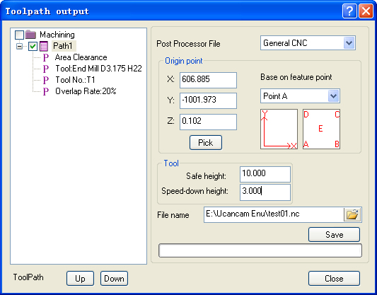
3. Set the parameters.
4. Click Browse to select the toolpath to be saved.
5. Name the file and click Save button.
Parameters
Post processor file: normally select “General CNC” is OK, if you want output the Toolpath in inch. Or your control system has special requirement, you shoul modify the post processor, for example moidify the “UNITS <mm>” to “UNITS <inch>” in the post processor file. If you need more help, you can contact with us.
Origin point: is the origin of the tool before machining is carried out.
For example:
originlower-leftuser lower-left the processing sheet
1. Custom: X, Y, Z are set to 0 (the origin based on lower-left corner of the layout), the actual machining position shown in Figure
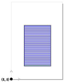
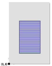
Figure 1 Figure 2
2. Base on feature points : You can select the position of the five points(A,B,C,D,E) , The location of the machining area is different according to the feature points selected.feature point
In order to make origin setting more flexible and the engraving more convenient, the function “Based on feature points” is available in Ucancam.
3. Save as before: Automatic memory the previous path position, and even restart the software.
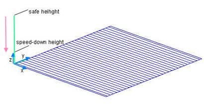
Safe Z height: is the distance between the tool position and the material surface when the tool is traveling above the material.
Speed-down Z height: is the distance between the material surface and the position tool beginning to decelerate.