Ucancam Engraving Software is a professional solution to CAD and CAM. It is widely used in such fields as advertisements, exhibition, decoration, artwork, moulds, seal-making, signs,gifts, architectural moulds, wood working, etc.
CAD
|
Drawing & Editing There is a powerful drawing and editing function in ucancam. Ucancam supports the feature point snapping、dynamic navigation、feature point aligning. many files can be imported into Ucancam, such as vector files: dxf, eps, plt, AI and bitmap format files: jpg, bmp, tif, png. |
|||||||||
|
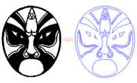
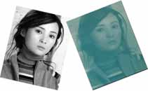
Image processingFunctions of image processing include Image tracing, Convert into grayscale image, Threshold, Brightness and Contrast adjustment. With these functions, you can extract contour of the figure, and then get the target cutting figure you want after node editing. | |||||||||
|
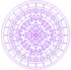
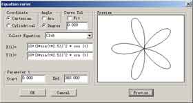
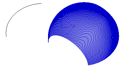
Equation Curve The software can automatically generate the curve described in the equation like this:
|
|||||||||
|
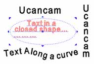
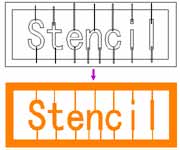
Text editingText can be rotated, scaled, moved, sheared, arranged along curves, etc. and can be edited again in text edit mode after these transformations. Besides, text input in a frame is also available, with automatic line feed. | |||||||||
|
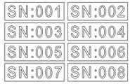
Serial number textThis function is used for making some designs of serial number texts. | |||||||||
|
|
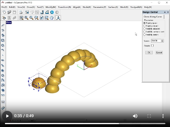
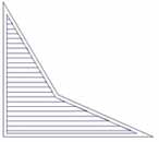
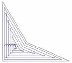
Duplication along a curve A kind of duplication tools, you can arrange the objects along a line or a curve. With these functions, you can work out well-regulated and handsome graphs. (More) | |||||||||
|
|
|
|||||||||
|
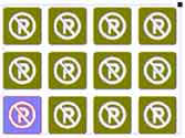
Array duplicationArray duplication function, modify the parameters of rectangular and circular duplication, dynamicly display the updated results, more intuitive, more convenient.(More) | |||||||||
|
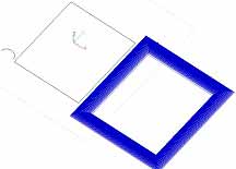
Artistic transformationJust like the changeful life. We have to do some complex change when design. Here we offer Perspective Distortion, Envelop Distortion, Push and Pull Distortion and Twist Distortion. (More) | |||||||||
|
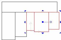
Locate and align in draggingWhile moving, scaling entities, if you hold Atl key, Ucancam can snap feature point as the start, end point of moving, allows you movling precisely, So as to realize fast nesting.(More) | |||||||||
|
Boolean operationBoolean operation includes join, common, not common and subtract. | |||||||||
|
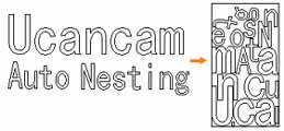
Auto nestingParameters setting such as kerf width, clearance and Iteration count; Nesting method setting: starting point (Left bottom, Right bottom, Left up, Right up), direction: X direction and Y direction; Precise calculation, such as in hole nest, to improve the efficiency of working and utilization rate of material. | |||||||||
|
Bumpbump the selected object to the top \bottom\left\righ of the other object rapidly, you can maximize the cutting materials ,reduce waste .(More) | |||||||||
|
Node editingFunctions in node editing include: add, delete, disconnect, connect, close, convert to line, convert to curve, smooth, symmetry, align, start point, auto remove points, fillet, and vertical. | |||||||||
|
TrimYou can trim out any parts you do not need by the user-friendly trim. | |||||||||
|
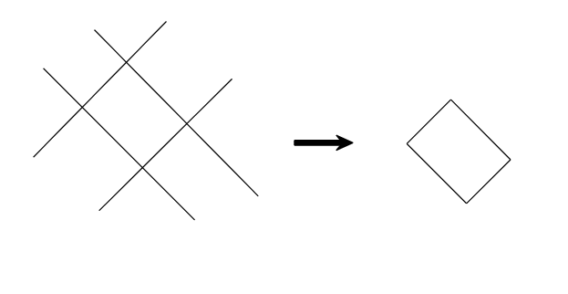
Extract Loop | |||||||||
|
ParametricGeometry constraint and dimension constraint.(More) | |||||||||
|
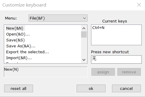
Hotkey customize. | |||||||||
|
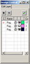
Layer managementIn Ucancam, you can create graphs on different layers that can exist together. You can add or delete layers so as to perform operations on many objects at the same time.(More) |
CAM |
||||
| Toolpaths are calculated quickly and accurately. Ucancam provides a Tools Library where users can choose, edit, add or delete a tool. Various machining solutions are available. Users can apply toolpath simulation to check whether toolpaths are valid and to preview machining results. These simulation functions are also useful to reduce trial cutting times and cut down machining costs and help users to get valid and effective machining results. | ||||
|
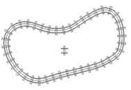
Profile machiningProfile Machining is widely used for incising. It includes On Line, Outside, and Inside machining. | |||
|
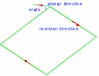
RampRamp is to plunge in a certain angle. Tools goes into the material not in a vertical direction but in slanting direction so that the tool will not be destroyed or broken because of force during entering material. This also ensures that no mark or scar be left on the surface of the material. | |||
|
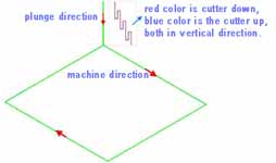
Pecking plungeWhen using Pecking plunge, the tool goes into a certain depth into the material, and then goes up to a certain height, and repeat this process when cutting the material. Pecking plunge prevents the tool breaks especially when cutting hard materials. | |||
|
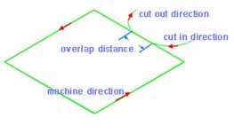
Lead in/outWhen using Lead in/out, the tool first goes into a certain depth outside of material, and then cuts into the side of the material. | |||
|
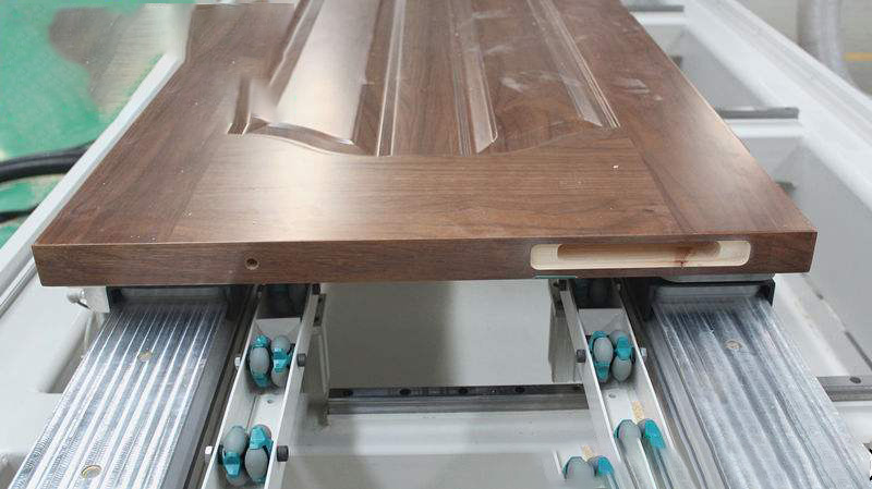
Oscillation:The difference with traditional machining is that the tool is cutting materials along both the X,Y plane and the Z axis direction,which makes full use of and protects the tool and improve the effiency of cutting. | |||
|
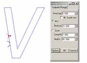
Toolpath plungeYou can modify the start point of profile path by click the start point, and keep the left mouse key down, drag the mouse to move the start point. And the same time the plunge will be modified by the parameter of dialog. | |||
|
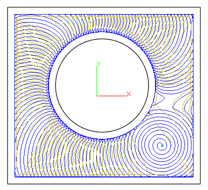
Trochoidal toolpathin profile machiningThe Trochoidal Toolpath is designed especially for brittle materials such as glass or granite or extremely hard materials that generate a lot of heat upon cutting. The Trochoidal Toolpath produce a circular toolpath at high feed rates with low load on the tool, therefore keeping the heat down while providing for longer tool life. | |||
 raster raster
|
 offset offset
|
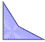 Spiral Spiral
|
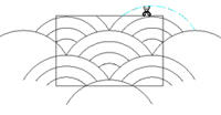
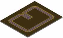
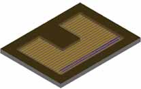
Area ClearanceArea Clearance is to mill an area in the material. There are two types of milling: raster, offset, Spiral. It is commonly used in our work.Offset (a maching strategy of Area clearance) has changed the line-transition into arc-transition and the small arc has been added as a transition for sharp corners , make it comfortable for high-speed milling. | |
|
Trochoidal Slotin area clearanceSlot milling is very difficult in area clearance. because
the tool is in double side cutting.but in ucancam the trochoidal
toolpaths are automatically added to mill slots in double
side cutting. and the feedrate speed is reduced , finally
protect the tool from breaking out .
|
|||
 |
|
Adaptive Mill |
||
|
|
||||
|
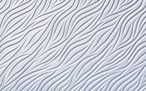
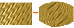
Flute Machining flute-shaped effects can be achieved through the silk texture machining on regular or irregular, scattered or disorderly straight lines and curveilinear lines in three ways: middle wider,start wider and end wider. | |||

|
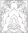
3D Corner Engraving3D Corner Engraving is to make the surface of the material smooth and to ensure the definition, precision and 3d effect of the machined object. It is mainly used in seal engraving and engraving of characters with special effects. 3D Corner Engraving includes top and bottom engraving, and the difference between them is the size of the machining area. | |||
|
|
||||
|
Midline MachiningMidline machining is to machine along the middle axis of the drawing. | |||
|
DrillingYou can Drilling on points, on curves, on the center of object or in region. | |||
|
Insert and InlayThis is a special function of engraving. It is an important measure to make sign marks and craftworks. | |||
|
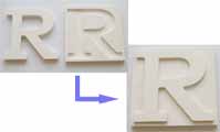
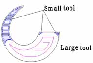
Intelligent machining Efficiency in milling can be greatly improved when applying Intelligent Machining. Two different tools can be chosen from the toolpath, the tool with lager diameter will be used for rough machining, and the smaller one will be used for precision machining. In the first machining, the speed is greatly improved, and after the second process, you will get what you want. | |||
|
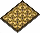
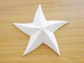
Prism machiningBy prism machining, it becomes easier for you to make characters with prism effect, and sign mark. Toolpaths can be created quickly and efficiently. If you want to make a massive work, it can be machined layer by layer, and you can fit them together when finished. There are two kinds of angles for you to choose, rounded angle and cusp angle. The prism will display clearly. Prism machining is quick to learn and easy to use. | |||
|
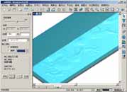
Embossing machiningEmbossing machining is mainly used in making relief. There are two modes in embossing: concave relief machining and convex relief machining. With ease operation, you will get accurate relief. It is widely used in such fields as advertising sign, sign board, breast card, furniture, metallic moulds, printings, etc. | |||
|
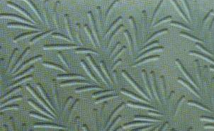
Image dot machiningImage dot machining is to engrave the object after the image is converted into grayscale image. Dots are made on the material based on the different grayscale value. The higher the grayscale value is, the deeper and bigger the dots are, and vice versa. | |||
|
Image relief machiningImage relief machining is to engrave the object after the image is converted into grayscale image. The machining is based on brightness level. Min brightness depth and max brightness depth are the depth by which the tool goes into the material. Horizontal/vertical machining is the direction of the tool path. | |||
|
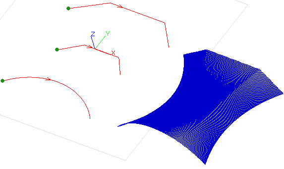
Loft surface Toolpathcreate toolpath between multile section curves .
|
|||
|
Revolve surface Toolpathprofile curve revolves with axis line. | |||
|
sweep surface Toolpaththe section curve sweeps along the drive track curve . | |||
|
Toolpath Trim | |||
|
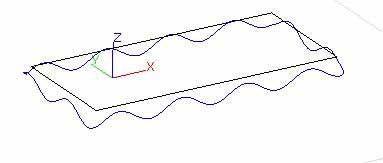
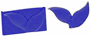
Toolpath artistic transformPerspective Distortion and Envelop Distortion can support the toolpath transform. especially can be applyed to the waveboard toolpath. | |||
|
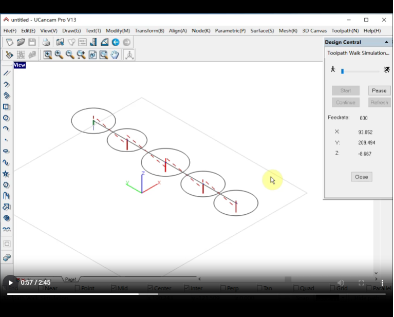
Toolpath simulationMachining process can be previewed through toolpath simulation, thus avoiding trial cutting and reducing cost. This function is helpful for choosing a proper machining type. | |||
|
|
Horzontal Mill: Tool axis: X: mill YZ plane。 Tool axis: Y: mill XZ plane | |||
|
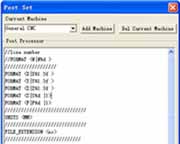
Post ProcessorThe Post Processor is a programme which converts the tool path in some standard neutral format into the format requried by a specific machine control system. Such as Biesse, CAMtech, Fanuc, Homag, MasterWood, Microstep, NcStudio, RichAuto, SYNTEC, SCM, etc.(More) | |||